glacios_screening
This is an old revision of the document!
Table of Contents
The Screening Pipeline
1. Load the Grids
- Introduce your grids in the cassette
- Cassette position 1 is dedicated to the Cross Grating Grid
- Grids are loaded with the C-clip toward position 1
- Load the cassette in the NanoCab. Make sure no contaminant (fiber, hair) entered the NanoCab.
- Remove the NanoCab
2. Setup Serial-EM
- Start Serial-EM software
- On the microscope computer, turn on the SerialEM server (if not already running)
 .
. - On the camera computer, turn on the serialEM install that match your method (SPA or uED)
 .
.
- Run the master script
- In serial-EM: script tab > run > Master (starts automatically with serial-EM).
- Select your directory in /data/users/your_directory/ and create your working directory
- Position of the first grid = position in the cassette where you loaded your first grid (This should be at least position 2, since position 1 is occupied by the Cross Grating Grid)
- Do you want to screen ? Yes
- Number of Grids = the number of grids you have loaded in the cassette
- Provide all grid names one by one
- Menu: Navigator > Open
- If the Imaging states window does not open with the Navigator window go to Navigator > Open imaging states
- Load platform or user settings
- Menu: Settings > Open > SerialEM_Settings_SPA
3. Record Atlases
- Setup the microscope for recording the Atlases
- On TEM user interface (TUI).
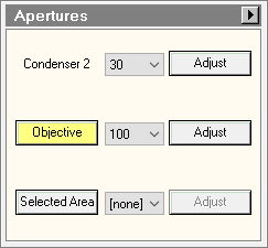
- Autoloader or Tune tab > Apertures panel : select condenser 2 150μm. Make sure Objective and selected area apertures are out (None status).

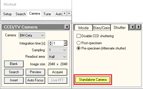
- Camera tab > CCTV/Camera panel > Shutter: make sure “Standalone Camera” is yellow. Otherwise, press on it.
- On Serial-EM.
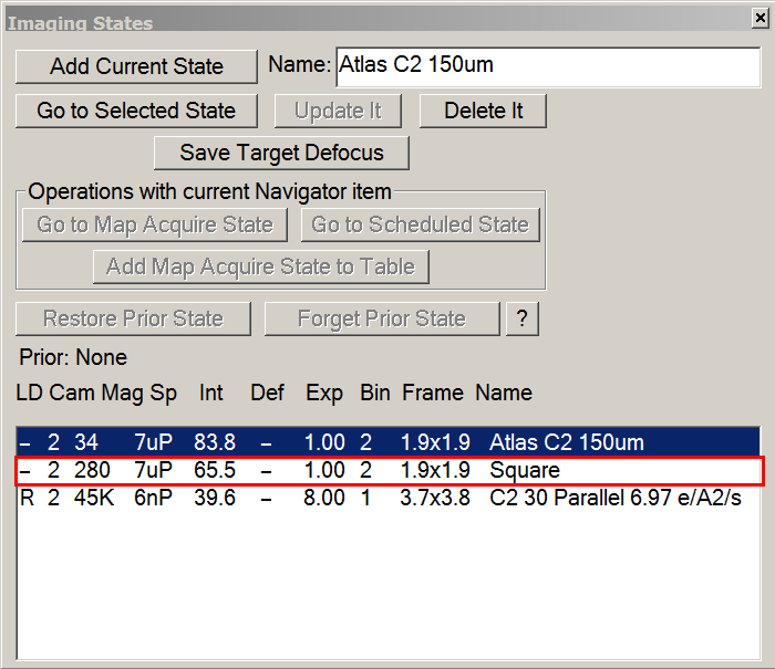
- Imaging States window > double click on Atlas C2 150 μm.
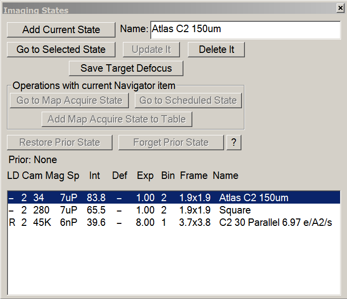
- On the microscope computer, make sure beam settings were updated according with Atlas imaging state.
- Setup montage parameters
- in Navigator tab > Montaging & Grids > Setup Full Montage
- Make sure magnification is set to 34X.
- Make sure binning is set to 2.
- On Glacios + K2,number of pieces should be 6*6 with an overlap of 15%-20%.
- Make sure other settings are in agreement with the Montage setup window bellow.
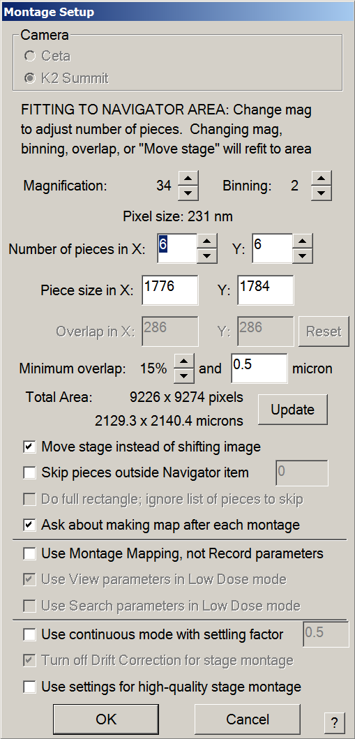
- Press OK > The file Properties window will open.
- If you are screening more than 10 grids, change 360 to 3600 in Maximum number os sections.
- Make sure settings are in agreement with the image of the window bellow.
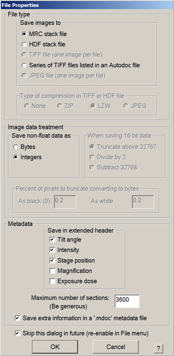
- Press OK, then save the mrc file in the work directory with a meaningful name i.e. “Atlases.mrc”.
- Manually collect atlases or run the gridmaps script
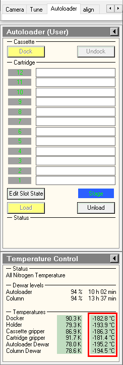
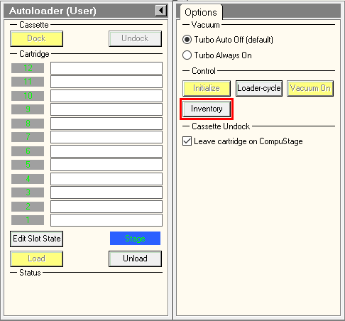
- Optional: Manually run cassette inventory
- After grid introduction, the autoloader initialization takes a few minutes.
- in the TUI, Make sure Autoloader elements temperatures are colder than -170°C. This is particularly important for the cartrige gripper, the autoloader element which grap the specimens.
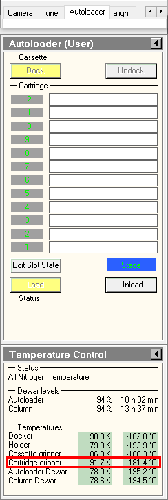
- in the TUI, press on Inventory button and wait until autoloader finishes the inventory. If you did not load a full cassette, you can press on stop inventory once the last loaded position was mapped.
- Automatically collect atlases with the gridmaps script
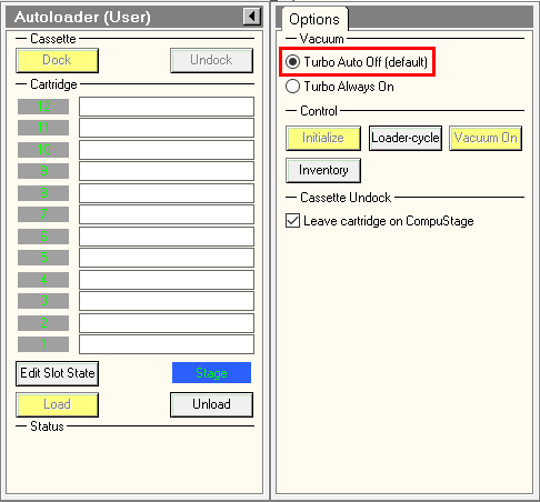
- To fasten Atlases acquisition, turn on turbo always on in TUI.
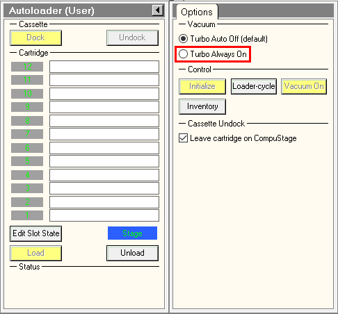
- In Serial-EM Script tab > run > gridmaps.
- The interface will ask three questions:
- Did you insert 150 μm C2 aperture ? : if not, refers to section 3.1, then press Yes.
- Please switch on the 'Standalone camera' in the camera/shutter menu in - only press 'OK' if it's done: In TUI, buttom must be yellow. Otherwise, press on it.
- Do you want to launch the inventory with a 16min delay ? : Look at the autoloader temperatures as indicated in section 3.1.a. If Cartridge gripper is colder than -170°C, press No. Otherwise, wait for temperature to be cold enough OR press Yes.
- Wait to see the few first Atlas tiles.
- Doing the Atlas for one grid takes approximately 10 minutes.
- Manual Atlas collection
- This is to run a grid map on a single grid.
- In the Montage Controls Panel, press Start.

- Once the atlas run is done, make sure it had been saved as a map in the navigator windows. Otherwise, press New Map in the navigator windows.

4. Select and Load a Grid
- Look at your Atlases and select the first Grid to screen
- Double click on each grid map in the navigator window
- Decide the grid you wish to screen first
- Introduce the Grid in the column
- In TUI, select the cassette position of the grid to be loaded, then press on Load.

5. Record square maps
- Setup the microscope for Squares imaging
- On TEM user interface (TUI) : Autoloader or Tune tab > Apertures panel : select condenser 2 30μm or 50μm.

- On Serial-EM : Imaging States window > double click on Square imaging state.
- On the microscope computer, make sure beam settings were updated according to Atlas imaging state.
- (Optional) Determine the overall eucentric height.
- In Serial-EM, center a square in the middle of the grid.
- add a marker (green cross) by left-clicking on a square.
- in the navigator windows press the go to marker button. Wait for the stage to reach the specified position.
- take a record image.
- if the square is off-center: keep pressed the right mouse button, grab the center of the square to the center of the screen, and release the button. Wait for the stage to reach its position.
- In Tasks tab > Eucentricity > press on Rough Eucentricity.
- Once eucentric height was determined, in navigator windows, select the line of the corresponding atlas and press on Update Z button.
- Correct for the coordinate discrepancy between Atlas and Square magnifications
- In the Navigator windows, double click on the Atlas line to load it.
- On the Atlas, look for the feature which is easily recognizable. It is recommended to choose a feature in the vicinity of the area of interest.
- Add a Point on the feature
- In the navigator windows, click on Add Points. The button Will change to Stop Adding.

- Click on the chosen feature.
- In the navigator windows, click on Stop Adding.
- Make sure the Point is selected in the Navigator windows.
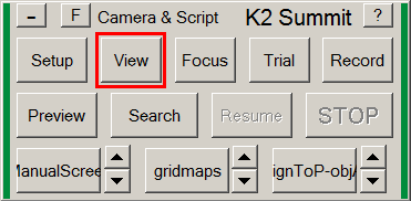
- In the Camera & Script panel, press on Record.

- Find the feature in the newly recorded image. If necessary, recenter the feature with the same method presented in section 5.2.d.
- Add a Marker on the chosen feature, i.e. simply do a left click which will draw a green cross.
- Make sure the Point is still selected in the Navigator windows.
- In Navigator tab, click on Shift To Marker…. A new windows will open, indicating the X and Y translation (in um) to apply to align the feature in at square magnification to the one at Atlas magnification. If this value make sens, i.e X and Y shifts are in the 10 → 50 um range, press OK.
- If you did a mistake, like applying the shift with an atlas/square map selected instead of the point, the sift can be deleted in Navigator tab > Undo last Shift.
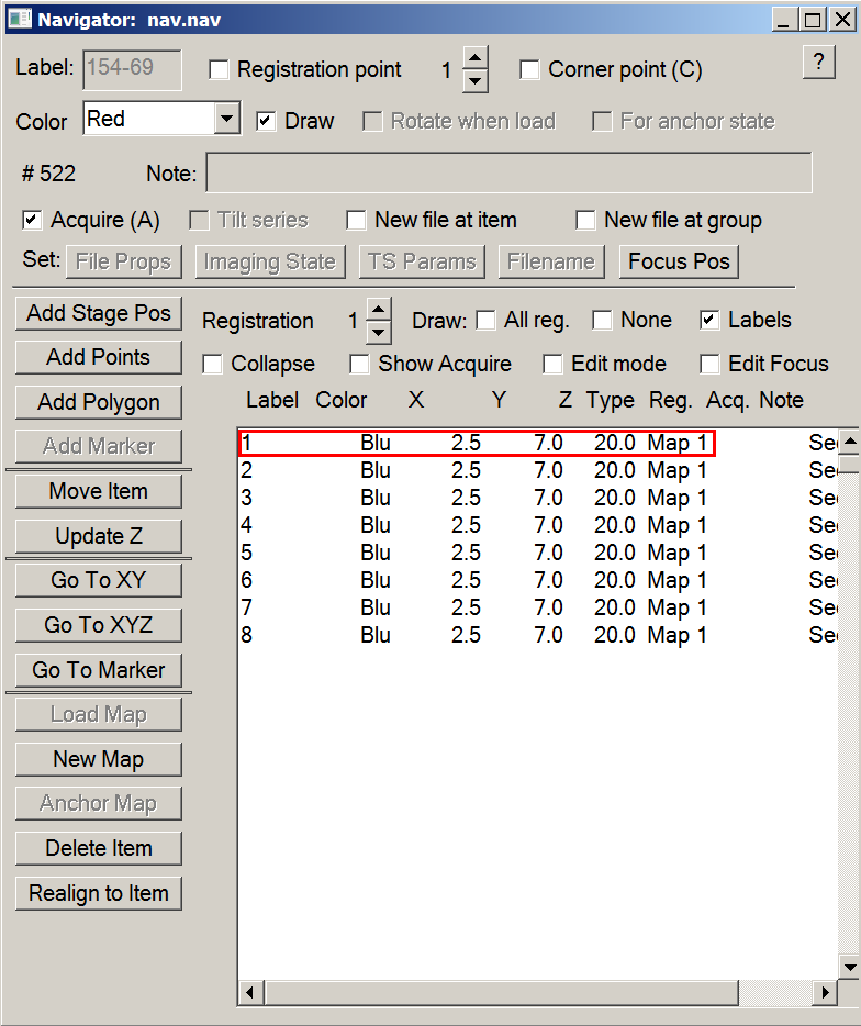
- Select squares to be mapped.
- Load the Atlas.
- Add Points in the middle of all the squares that you wish to map.
- Change Points status to Acquire.
- In Navigator windows:
- Check the Collapse radio button.

- Select the group of items.
- Check the Acquire (A) radio button to activate the Points.

- Uncheck the Collapse radio button. All Points should display a A.

- (Optional) Go through all the points to correct for centering.
- In the navigator windows:
- Select the first Square Point.
- Press Go to XY button, then wait for the stage to reach the square.
- In the Camera & Script Panel, take a Record.
- If the Point if off-centered:
- Make sure the Point which is selected is the one you want to move.
- click on Move Item button in the Navigator windows. The button will change to Stop Moving.

- Click in the middle of the Square.
- Click on the Stop Moving button.
- Repeat these steps for all the Square Points.
- Automatically collect squares maps and determine their eucentric height.
- Menu > File > Open New. Save a mrc file wherein Square maps will be saved.
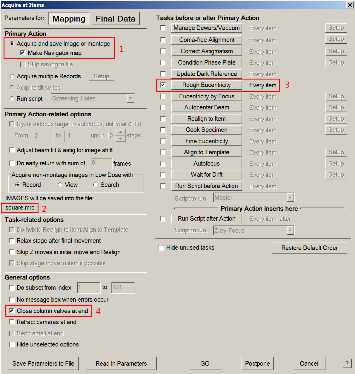
- In menu > Navigator tab > Acquire at Items: start square mapping
- Tick Acquire and save image or montage & Make Navigator map radio buttons.
- Make sure that IMAGES will be saved into the file: directs toward the previously saved mrc file.
- Tick the Rough Eucentricity option and make sure it will be performed at every item.
- If you plan to leave the microscope room while it records squares maps, tick the close column valves at end option.
- Press GO.

6. Prepare Serial-EM for screening
- Setup the microscope for Low Dose imaging
- On TEM user interface (TUI) : Autoloader or Tune tab > Apertures panel : select condenser 2 30μm and Objective 100μm.
- On Serial-EM : Imaging States window > double click on C2 30 Parallel imaging state.

- Correct for the coordinate discrepancy between Square and Low Dose View magnifications
- In the Navigator windows, double click on a Square line to load it.
- On the square, look for the feature which is easily recognizable.
- Add a Point on the feature
- In the navigator windows, click on Add Points. The button Will change to Stop Adding.
- Click on the chosen feature.
- In the navigator windows, click on Stop Adding.
- Make sure the Point is selected in the Navigator windows.
- In the Camera & Script panel, press on View.
- Find the feature in the newly recorded image. If necessary, recenter the feature with the same method presented in section 5.2.d.
- If you have trouble finding the feature, use the fluo-screen and the joystick:
- lower the fluorescent screen with the console button indicated in the lower panel of the TEM User Interface.
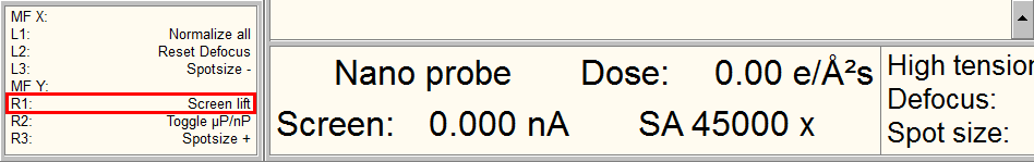
- with the joystick, move the stage so that the desired feature is in the green square (K2 area) on the fluorescent screen.
- Lift up the fluorescent screen with the same console button.
- Add a Marker on the chosen feature, i.e. simply do a left click which will draw a green cross.
- Make sure the Point is still selected in the Navigator windows.
- In Navigator tab, click on Shift To Marker…. A new windows will open, indicating the X and Y translation (in um) to apply to align the feature in at square magnification to the one at Atlas magnification. If this value make sens, i.e X and Y shifts are likely lower than 10um, press OK.
- If you did a mistake, like applying the shift with an atlas/square map selected instead of the point, the sift can be deleted in Navigator tab > Undo last Shift.
- Select the focusing area
- Center a hole. If you plan to record images at the hole periphery, center the camera closer to a hole edge.
- Take a View and correct position if necessary.
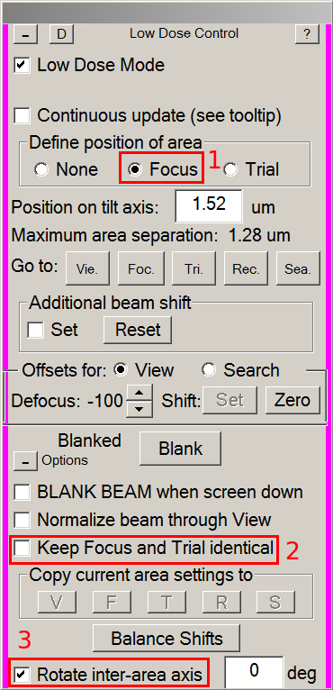
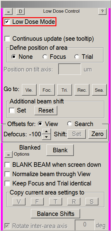
- In the Low Dose control panel:
- Tick the Focus radio button (1).
- Make sure Keep Focus and Trial Identical is not thicked (2).
- Make sure Rotate inter-area axis is ticked (3).
- On the view image, left-click between four holes. This will move the focusing area to this place.

- Tick the None radio button to leave the focus display.
- Create a reference hole
- Center a hole. It must be non-empty, with an ice thickness representative of your grid, and free of ice contamination. If you plan to record images at the hole periphery, center the camera closer to a hole edge.
- Take a View and correct position if necessary.
- Adjust the camera field of view to capture a single hole in the image.
- Note: For gold grids, have a little piece of the surrounding holes help in downstream alignment.
- Press Setup in the Camera & Script panel.
- Tick the View radio button.
- Adjust the Camera field of view with the Area Size buttons.
- Press Acquire to take a snapshot and Adjust the area size if necessary.
- In the Buffers Control panel, press on P to save the reference hole image in this buffer.
- Center the Objective aperture.
- Note: Be very careful ! for this step, you will need to work in diffraction mode. Direct exposure of the camera sensor with the direct beam may result in damages of the electron detector.
- Center on carbon or gold support film.
- In the Low Dose Control panel, press the Rec. button to switch the beam from View to Record setup.
- Lower the fluorescent screen as described in section 6.2.
- On the microscope Console, press the Diffraction button.
- Recenter the direct beam in the small red circle of the fluorescent screen with multifunction X & Y knobs.
- With the mouse knob, change the sensitivity of the fluorescent screen to make the objective aperture shadow visible.
- In the TEM User Interface, on the Apertures panel, press the Adjust button next to the Objective aperture selector.
- With multifonction X & Y knobs, center the objective aperture around the direct beam.
- Deselect the adjust button in the Apertures panel.
- Turn off diffraction mode.
- Lift the fluorescent screen.
- Center the low-dose beams on the camera.
- Move to a empty area (empty hole or brocken square)
- In the Low Dose Control panel, tick Continuous Update.
- Switch to record beam with the Rec. button.
- On the console, press the Eucentric Focus button.
- Lower the fluorescent screen.
- In TEM User Interface > Tune or Autoloader tab > Direct Alignments panel: press on beam shift.
- With multifunction X & Y knobs, center the beam on the fluorescent screen, then press Done.
- Switch to View beam with the Vie. button. Tick Set in Additional beam shift. View beam only need to be centered once.
- With the trackball, center the view beam on the fluorescent screen.
- Center the Record beam again as described above.
- Switch to Focus beam (Foc. button) and change its diameter with the intensity knob according with the desired focus surface (depends on your hole spacing).
- Center focus beam as explained for the view beam (with Set ticked and trackball).
- Switch to Trial beam (Tri. button) and change its diameter with the intensity. Trial beam will be used for auto-centering and its diameter should fit in the camera field (green square) on the fluorescent screen.
- Repeat Record (Beam Shift + M X/Y), Focus and Trial (Set ticked + Trackball) centering until all beams stay centered.
- Untick Continuous update on the Low Dose Control panel. </div>- In an empty hole or a broken square: Menu > Scripts > run > DatasetDefineVacuumIntensity - measure the dose rate and set up record parameters. ==== 7. Start screening and analyze the results ==== - ++Select a few target holes on each square
- Add Points on the desired holes
- Stop adding and Collapse
- Press A key to define acquisition at all points and Collapse again
- Manually screen your targets or run the script Screening Holes- Menu: Navigator > Acquire at Items > Screening-Holes (uncheck Rough Eucentric)
==== 8. Load the next grid ==== - Double-click on the desired grid in the TUI - Go back to step 4 ==== 9. End your screening session ==== - Save your Navigator - Close your Navigator - Load the Cross Grating Grid in the column (usually in position 1 of the cassette) - Remove the cassette with your grids from the autoloader in the NanoCab - Remove the cassette and your grids from the NanoCab
glacios_screening.1673878320.txt.gz · Last modified: (external edit)